Historical Perspective
Part One | Part Two | Part Three | Part Four | Part Five | Part Six | References
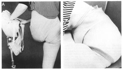 FIG21B-1
A silicone rubber socket indicating the amount of flexibility present.
Only the weightbearing portion is reinforced with rigid materials. B. the
flexibility of silicone rubber aids comfort and increases freedom of movement
such as forward bending.(From Van der Waarde T: Orthot Prosthet 1984; 38:29-31.
Used by permission.)
The traditional device prior to 1954 consisted of a molded leather socket with a laterally placed locking hip joint called a tiltingtable prosthesis. Often shoulder straps were required for suspension. Gross pelvic thrust was required to propel the prosthesis, and a vaulting gait was common. A radical departure, later termed the "Canadian" design, was introduced by McLaurin in 1954 (Fig21B-2). This unique approach demonstrated the feasibility of using unlocked hip, knee, and ankle joints that relied on biomechanics to achieve stancephase stability while permitting flexion at the hip and knee during swing phase. This is now the standard for prosthetic fitting worldwide, and locking joints are very rarely necessary. A molded plastic socket encloses the ischial tuberosity for weight bearing, extends over the crest of the ilium to provide suspension during swing phase, and affords excellent mediolateral trunk stability by fully encasing the contralateral pelvis.The prosthetic hip joint is attached to the socket anteriorly, and this results in excellent stancephase stability plus good swingphase flexion.
Hip Joint Mechanisms*
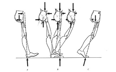
One of the inherent limitations of the Canadian design is that the prosthesis must be significantly short (1 cm+) to avoid forcing the amputee to vault for toe clearance. Figures 21B-3 and 21B-4 illustrate why this is so. At toeoff, the heel rises up during knee flex ion and pulls the hip joint firmly against its posterior (extension) stop. The thigh segment remains vertical until the knee has reversed its direction of motion and contacted the knee stop. Only then does the thigh segment rotate anteriorly and cause the hip joint to flex. In essence, the prosthesis is at its full length during midswing. Since the patient has no voluntary control over any of the passive mechanical joints, the prosthetist is forced to shorten the limb for ground clearance. In an effort to overcome this limitation, the hip flexion bias system was developed for the young, active amputee who wished to walk rapidly. At toeoff, kinetic energy from the coil spring is released, and the prosthetic thigh is thrust forward. Not only does this provide the amputee with a more normalappearing gait, it also improves ground clearance. As a result, the prosthesis can be lengthened to a nearly level configuration in most cases (Fig21B-5).
However, two potential problems have been noted with this approach. One is the development of annoying squeaks in the spring mechanisms after a few months of use, which sometimes tend to recur inexorably. A more significant concern is that as the spring compresses between heel strike and midstance, it creates a strong knee flexion moment. Unless this is resisted by a stance control knee with a friction brake or a polycentric knee with inherent stability, the patient may fall. Since the friction brake mechanisms lose their effectiveness as the surface wears, the polycentric knee is the preferred component with this hip mechanism.
Another hip joint option is the Otto Bock fourbar knee disarticulation joint mounted in reverse as proposed by Peter Tuil of The Netherlands (Fig21B-6). Benefits claimed are parallel to those expected from a polycentric knee unit: increased ground clearance during swing phase due to the inherent "shortening" of the linkage in flexion and enhanced stability at heel strike.
*The sections dealing with joint and foot mechanisms are reprinted, with minor modifications, from Michael J: Clin Prosthet Orthot 1988; 12:99-108.
We have divided this article up into sections for faster load times as follows:
Part One | Part Two | Part Three | Part Four | Part Five | Part Six | References